9 Results
View results:
Sort by:

With the RF-/TIMBER Pro add-on module, you can perform the vibration design known from DIN 1052 for the design according to EN 1995-1-1. In this design, the deflection under permanent and quasi-permanent action at the ideal one‑span beam may not exceed the limit value (6 mm according to DIN 1052). If you consider the relation between the natural frequency and the deflection for a hinged single-span beam subjected to a constant distributed load, the 6 mm limit value results in a minimum natural frequency of about 7.2 Hz.

The shear force resistance VRd,c without computational shear force reinforcement according to 6.2.2 of EN 1992-1-1 [1] or 10.3.3 of DIN 1045-1 [2] is calculated depending on the longitudinal reinforcement ratio. If the required longitudinal reinforcement from the bending design is used for the calculation of VRd,c, this leads to an underestimation of the shear force resistance without shear reinforcement in the vicinity of the hinged end supports. In contrast to the shear force, the required bending reinforcement decreases in the direction of the support. Furthermore, the actually inserted longitudinal reinforcement usually deviates significantly from the required bending reinforcement in the end support area (for example, in the case of non-staggered beam reinforcement).
In this technical article, a hinged column with a centrally acting axial force will be designed by means of the RF-/STEEL EC3 add-on module according to EN 1993-1-2. We will use the National Annex of Germany here.

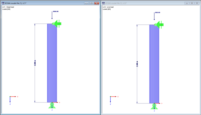
In this technical article, a hinged column with a centrally acting axial force and a line load acting on the strong axis will be designed by means of the RF-/STEEL EC3 add-on module according to EN 1993-1-1.
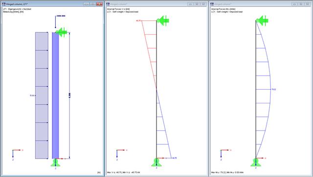
In this technical article, a hinged column with a centrally acting axial force and a linear load that acts on the major axis are designed according to EN 1993-1-1 with the aid of the RF-/STEEL EC3 add-on module. The column head and column base are assumed as a lateral and torsional restraint. The column is not held against rotation between the supports. The cross-section of the column is an HEB 360 from S235.

RFEM and RSTAB offer different options to model bored piles. One option is to display bored piles as single-valued supports or hinged columns. Another option is realistic modeling while taking the soil into account by means of applying a member elastic foundation. The two following examples will describe it in detail. However, pile base resistance, skin friction, and soil layers are not considered in this technical article.
![System and Loading According to [1]](/en/webimage/009455/2418877/01-en-png.png?mw=640&hash=c76563b459152b19c98197ea6ba342be89d9a5bc)
The product range of Dlubal Software contains various modules for design of steel and timber connections. The RF-/JOINTS Steel – Column Base add-on module allows you to analyse footings of hinged or restrained steel column bases. The fastener selection, foundation geometry, and material quality are crucial for the cost-effective and safe design of the column base.
![System and Loading According to [1]](/en/webimage/009634/2419765/01-en-png-png.png?mw=640&hash=5e657e3feb5c1bb6d21727468dd85d91e1c9f29f)
A structural analysis does not only determine and design internal forces and deformations. It also ensures that the forces and moments in a structure are generated in a reliable way and applied to the foundation. Dlubal Software provides a wide range of products for the structural analysis and design of steel and timber connections. The RF-/JOINTS Steel – Column Base add-on module allows you to design footings of hinged and restrained column bases. The design can be performed for column base plates with or without stiffeners.

For structural reasons, shear connections usually include fin plates or flange angles. Main and secondary beams arranged on the top edge require notching or long fin plates. Hinged end plate connections are often welded to the web.